
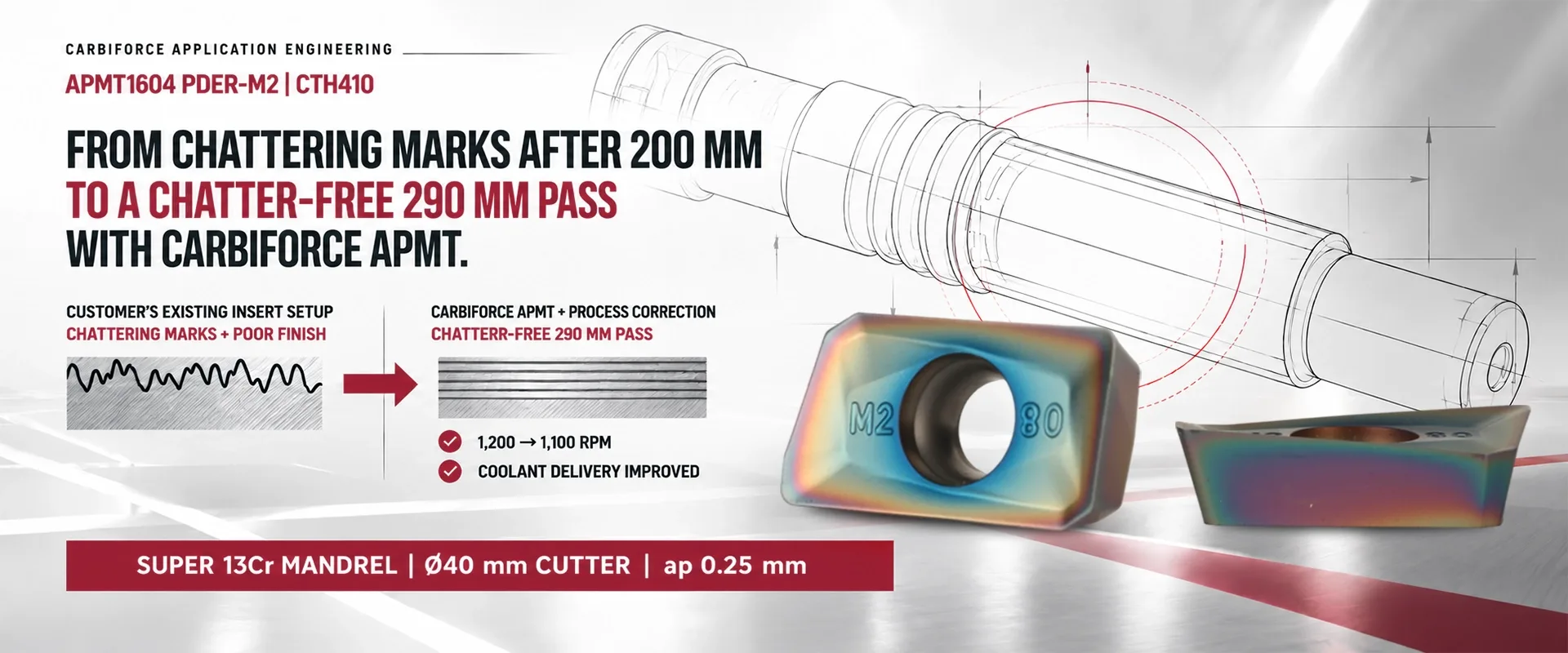
Learn about APMT inserts, specifications, types, pricing factors, and selection tips. Explore a real machining case where the APMT1604 PDER-M2 CTH410 insert achieved a chatter-free 290 mm pass on a Super 13Cr mandrel.
APPLICATION ENGINEERING RESULT
From Chattering Marks to a Chatter-Free Pass
Improving milling surface finish on a Super 13Cr mandrel with CARBIFORCE APMT1604 PDER–M2 | CTH410.
THE MACHINING CHALLENGE
During milling of a Super 13Cr mandrel, the existing insert produced chatter marks and poor surface finish after 200 mm of cutting. A controlled machining correction was introduced using the CARBIFORCE APMT1604 PDER–M2 insert with CTH410 grade.
Machining Performance Comparison
The Engineering Contribution
RPM was corrected from 1,200 to 1,100, along with improved coolant delivery. Together, these changes enabled the chatter-free 290 mm pass with the required surface finish.
Machining Application Details
Get a Solution for Your CNC Milling Application
Facing chatter marks, poor surface finish, surface variation or inconsistent carbide insert performance? Share your component details and current cutting conditions for an application engineering review.
The team can evaluate your machining challenge and discuss suitable tooling and process adjustments for your application.
WhatsApp: +91 70215 83452
Email: [email protected]
APMT1604 PDER-M2 CTH410 Inserts for Chatter-Free Milling
APMT inserts are commonly used in indexable milling cutters for metal machining applications. Selecting the correct insert geometry, grade, and cutting parameters is important when dealing with chatter marks, poor surface finish, and inconsistent milling performance.
The APMT1604 PDER-M2 CTH410 insert was used in an application involving the milling of a Super 13Cr mandrel. The initial setup produced chatter marks and poor surface finish after 200 mm. After a controlled tooling and process correction, the application achieved a chatter-free 290 mm pass.
This application case explains the role of the insert, its key identification details, important purchasing considerations and practical ways to troubleshoot milling problems.
What Is an APMT Insert?
An APMT insert is a positive-clearance, parallelogram-shaped indexable milling insert used with compatible milling cutter bodies. It is commonly used in applications such as shoulder milling, side milling and selected face-milling operations, depending on the cutter design.
The insert is replaceable, allowing a worn cutting edge to be changed without replacing the complete cutter body.
APMT Insert Full Form and Code Meaning
People searching for the APMT insert full form often want to understand what the letters and numbers represent.
APMT is an insert designation based on an ISO-style coding system. It is more accurate to explain it as a code identifying the insert's shape, clearance, tolerance and mounting or chip-forming features rather than treating it as a conventional acronym.
For the APMT1604 insert, the designation generally indicates:
A: Parallelogram insert shape with an 85-degree included angle.
P: Positive clearance designation, generally associated with 11-degree clearance.
M: Tolerance class designation.
T: Insert configuration with a hole and a chip-forming feature, according to the applicable designation.
16: Insert size designation.
04: Thickness designation in the applicable insert series.
The complete product code is important because additional letters can identify the cutting-edge configuration, chipbreaker, and manufacturer-specific geometry.
For example, APMT1604 PDER-M2 CTH410 identifies the insert configuration used in the Super 13Cr mandrel application described below. Always verify the complete code against the product drawing and cutter manufacturer's specifications.
APMT1604PDER-M2 CTH410 Insert Specifications
The following table summarizes the documented application details. Dimensions for the specific insert should be confirmed using its approved technical drawing.
Understanding APMT Insert Specifications
When reviewing APMT insert specifications, check the complete designation, insert dimensions, corner radius, cutting-edge configuration, grade and compatible cutter pocket.
Do not select an insert based only on the words APMT1604. Different suffixes and product series can have different geometries or dimensions, even when the main size designation looks similar.
Types of APMT Inserts
The types of APMT inserts available depend on the manufacturer's range, insert geometry, chipbreaker, corner radius and grade.
Common selection categories include:
APMT1135 inserts: A smaller size family used with compatible cutter bodies.
APMT1604 inserts: A larger size family used with compatible indexable milling cutters.
APMT roughing inserts: Configurations intended for suitable material-removal operations.
APMT finishing inserts: Configurations intended for suitable finishing conditions.
APMT semi-finishing inserts: Options designed for intermediate machining requirements.
The precise role of a particular insert depends on its complete product code and manufacturer's recommendations. Roughing, semi-finishing and finishing descriptions should be confirmed from the relevant product catalogue rather than assumed from the APMT designation alone.
APMT 16 Insert vs APMT 11 Insert
Searches for APMT 16 insert and APMT 11 insert often relate to choosing an insert for an existing milling cutter.
These are general size-family references, not guaranteed dimensions for every brand or model. The actual dimensions can vary by product design.
Important: APMT1604 and APMT1135 are not automatically interchangeable. Check the cutter body's insert pocket and the full insert designation before ordering.
How APMT1604 PDER-M2 CTH410 Helped Address Chatter Marks
The Problem: Chattering Marks After 200 mm
During the milling of a Super 13Cr mandrel, the existing insert setup produced chatter marks and poor surface finish after 200 mm.
The machining objective was to improve cutting stability and achieve the required surface finish over a longer pass.
Potential causes of chatter marks in CNC milling include tool or workpiece vibration, insufficient rigidity, unsuitable cutting parameters, insert wear, and inconsistent insert seating. The actual cause should be assessed for the specific machine and setup.
The Solution: Tooling and Process Correction
The APMT1604 PDER-M2 CTH410 insert was applied as part of a controlled machining correction.
Three tooling considerations supported the approach:
PDER-M2 geometry: Supported controlled cutting action and chip evacuation in the reported application.
CTH410 coating–substrate system: Was used to resist thermal and abrasive cutting-edge deterioration.
Secure insert seating: Helped maintain repeatable cutting-edge positioning over the extended cutting length.
The process was also adjusted by reducing spindle speed from 1,200 RPM to 1,100 RPM and improving coolant delivery.
The Result: Chatter-Free 290 mm Pass
After the combined tooling and process correction, the application achieved a chatter-free 290 mm pass.
The reported result improved from chatter marks and poor surface finish after 200 mm to a chatter-free pass over 290 mm.
This case illustrates why CNC milling surface finish problems should be investigated through a combination of insert selection, cutting conditions, tool stability and coolant delivery.
The result is specific to the stated application and should not be interpreted as a guaranteed outcome for every Super 13Cr machining operation.
How to Reduce Chatter in CNC Milling
If your machining process produces chatter marks, poor surface finish or inconsistent insert performance, review the complete cutting setup before changing several parameters at once.
Use this checklist:
Inspect the insert: Look for edge wear, chipping or damage.
Check the cutter and toolholder: Inspect tool projection, clamping and mechanical condition.
Review insert seating: Confirm that the insert is correctly positioned and secured.
Check workpiece rigidity: Review the fixture and workpiece clamping arrangement.
Evaluate spindle speed: Conduct controlled trials to identify more stable cutting conditions.
Review feed rate and depth of cut: Confirm that the parameters are appropriate for the tool, material and operation.
Check coolant delivery: Ensure that coolant reaches the cutting zone as required.
Record the results: Document successful settings so the process can be repeated.
These steps can help machining teams investigate how to reduce chatter in CNC milling without relying on a single adjustment for every application.
APMT Insert Price, Size Chart and Buying Considerations
APMT Insert Price
The APMT insert price depends on the insert size, complete designation, grade, coating or substrate system, supplier and order quantity.
For an accurate quotation, provide the full insert code, required grade and quantity. For this specific application, request pricing for APMT1604 PDER-M2 CTH410 rather than asking for APMT1604 alone.
APMT Insert Size Chart
An APMT insert size chart helps buyers match the insert to the cutter body.
Before ordering, verify:
Overall insert dimensions.
Thickness and mounting-hole dimensions.
Corner radius and cutting-edge configuration.
Chipbreaker and grade.
Compatibility with the existing cutter pocket.
Use the relevant manufacturer's drawing to confirm exact measurements. A general size chart should not replace a compatibility check.
APMT Insert HSN Code
Customers searching for the APMT insert HSN code should verify the correct classification for the actual product being supplied.
Indexable carbide inserts may fall under different classifications depending on whether they are unmounted carbide or cermet tips or another type of interchangeable tool. Do not assign an HSN code solely from the APMT name. Confirm the applicable classification with the supplier or a qualified tax professional before preparing an invoice.
Frequently Asked Questions for APMT Inserts
1. What is the APMT insert full form?
APMT is an ISO-style insert designation, not a conventional product acronym. Its letters identify the insert's shape, clearance, tolerance, and configuration. The complete code provides additional details about size and geometry.
2. What is the difference between APMT1604 and APMT1135?
APMT1604 and APMT1135 are different insert size families. Their dimensions and cutter compatibility differ, so the correct insert must match the cutter pocket and complete product designation.
3. What affects APMT insert price?
The APMT insert price depends on the exact model, grade, geometry, supplier and order quantity. Request a quotation using the complete insert code to avoid confusion between variants.
4. How do I check APMT insert specifications?
Review the complete product designation, technical drawing, dimensions, corner radius, grade and compatible cutter details. Confirm the information with the product catalogue before ordering.
5. What was the result of the APMT1604 PDER-M2 CTH410 application?
The reported application achieved a chatter-free 290 mm pass on a Super 13Cr mandrel, following a reduction in spindle speed from 1,200 to 1,100 RPM and improved coolant delivery.
6. How can I choose the right APMT insert for milling?
Choose the insert according to the cutter body, workpiece material, operation, required surface finish, insert geometry and recommended cutting conditions. Confirm compatibility using the complete product code and technical documentation.
Conclusion
APMT inserts play an important role in indexable milling applications. The APMT1604 PDER-M2 CTH410 insert helped achieve a chatter-free 290 mm pass on a Super 13Cr mandrel after tooling and cutting-condition adjustments. Selecting the correct insert geometry, grade, and machining parameters can help improve surface finish and machining stability.