
Stainless-steel machining can become challenging when a component requires multiple cutting passes, produces inconsistent chips, or delivers low output per cutting edge. Selecting the right insert geometry, carbide grade, and cutting parameters can help address these issues.
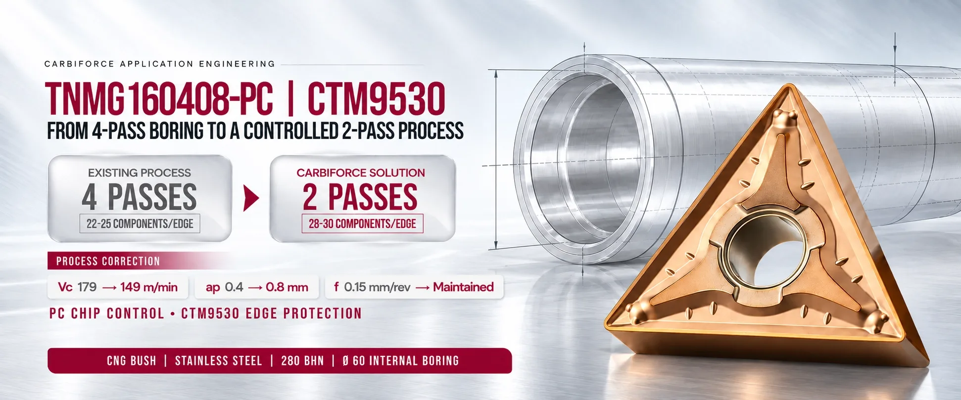
In this application case study, we evaluated a TNMG160408–PC insert paired with the CTM9530 grade for machining a 280 BHN stainless-steel CNG bush with a Ø60 mm internal bore. By coordinating the cutting tool and machining conditions, Carbiforce Engineering reduced the number of passes and improved component output per edge.
Application Case Study: Four Passes Reduced to Two
For the 280 BHN stainless-steel CNG bush with a Ø60 mm internal bore, the previous setup required four passes and delivered approximately 22–25 components per cutting edge.
Carbiforce Engineering paired the selected insert with revised cutting conditions.
Application result:
Machining passes reduced from 4 to 2.
Output increased from 22–25 to 28–30 components per cutting edge.
The revised chipbreaker and cutting parameters supported controlled machining at the increased depth of cut.
The trial was conducted on a Turning Centre ACE using a BB S25–MTJNL16 boring bar, with a 35 mm cutting length, 55 mm tool length and wet machining.
These results apply to the stated trial conditions. Actual results can vary with machine rigidity, workpiece material, tool overhang, coolant delivery and cutting setup.
TNMG Insert Specification and Nomenclature
Understanding insert coding helps machining teams identify the correct product and communicate requirements to their tool supplier.
The designation TNMG160408 contains information about the insert's shape, clearance, tolerance, clamping style and nominal dimensions. The exact interpretation should be checked against the applicable ISO designation and product catalogue.
The complete TNMG insert specification also depends on the manufacturer's dimensions, chipbreaker, grade, and application recommendations. Confirm the exact dimensions in the product datasheet before ordering.
The Machining Problem: Too Many Passes and Limited Tool Life
The component was previously machined in four passes. Each cutting edge produced approximately 22–25 components before replacement, limiting productivity and increasing the need for tool changes.
The application required a practical solution that could:
Reduce the number of machining passes.
Improve component output per cutting edge.
Maintain controlled chip formation.
Support consistent cutting performance during internal machining.
Balance productivity with cutting-edge durability.
Instead of changing the insert alone, the application required a coordinated review of insert geometry, grade selection and cutting parameters.
TNMG Carbide Inserts: Selecting the Right Geometry and Grade
TNMG turning inserts are commonly used for external turning, facing and suitable boring applications, depending on the tool holder and setup. Their triangular shape provides three usable cutting corners when the insert design and indexing arrangement permit it.
For this CNG bush application, Carbiforce Engineering selected the TNMG160408–PC | CTM9530 combination.
The selection focused on two key elements:
PC chipbreaker geometry: Supported controlled chip formation under the revised cutting conditions.
CTM9530 grade: Its carbide substrate and Si-containing AlTiN PVD composite nano-coating were selected to support resistance to heat and abrasive wear at the cutting edge.
The coating specification provided for this grade is 3–5 μm thickness and HV 3,200–3,700 hardness. These values describe the supplied coating specification and should not be interpreted as a guarantee of tool life in every application.
TNMG Insert Full Form
The term TNMG insert full form refers to the meaning of the letters in the insert's standardized designation. T identifies the triangular shape, N the zero-clearance angle, and M the tolerance class. G identifies additional construction details defined by the insert coding standard.
For a complete reference, consult the relevant ISO insert designation guide or a manufacturer-approved TNMG insert full form PDF. The final letter and numerical dimensions should be interpreted using the applicable standard rather than assumed from the code alone.
TNMG Insert Types, Grades and Size Selection
Different machining operations require different combinations of geometry and carbide grade. The appropriate selection depends on the workpiece material, cutting conditions, machine rigidity and required surface finish.
Common selection factors include:
TNMG insert grades: Choose a grade recommended for the workpiece material, cutting speed, feed, depth of cut and expected wear conditions.
TNMG inserts for stainless steel: Consider a grade and chipbreaker designed for the stainless-steel machining conditions involved.
TNMG inserts for steel: Match the insert's application range to the steel grade, hardness and operation.
TNMG negative turning inserts: Consider these when the holder, cutting conditions and required edge strength suit a negative insert arrangement.
The TNMG 160408 designation identifies a commonly used insert size family, but the same designation can be available in different grades and chipbreaker designs. Confirm compatibility with the holder and boring bar before selecting a replacement.
TNMG Insert Sizes and Size Chart
A TNMG insert size chart can help compare insert designations, thicknesses and corner radii. However, dimensions and availability can vary by manufacturer and product series.
The required TNMG insert length and other physical dimensions should be taken from the official dimensional drawing. The size number should not be treated as a direct measurement in millimetres without checking the applicable catalogue.
TNMG Insert Angle Chart
When reviewing a TNMG insert angle chart, check the insert's included angle, clearance angle and the cutting approach angle created by the tool holder. These values affect access, edge strength, cutting forces and chip formation.
The insert's triangular shape does not by itself determine the approach angle in the machining operation. That angle depends on the tool-holder geometry and setup.
How to Choose the Right TNMG Insert for Your Application
When machining output is low or cutting edges wear too quickly, review the full process rather than selecting a tool based.
Identify the workpiece material: Confirm the material grade and hardness.
Review the current machining process: Record the cutting speed, feed, depth of cut and number of passes.
Check chip control: Select a chipbreaker suited to the operation and expected chip thickness.
Match the grade to the application: Use the recommended grade range for the material and cutting conditions.
Confirm tool compatibility: Check insert dimensions, clamping arrangement and holder designation.
Evaluate the result: Track passes per component, components per edge, surface finish and cutting-edge wear.
This process helps identify whether the main limitation comes from insert geometry, grade selection, cutting parameters or the machine setup.
TNMG Insert and Wholesale Supply
The TNMG insert depends on the insert size, carbide grade, chipbreaker, coating, quantity and supplier. The TNMG carbide insert should therefore be compared alongside application suitability and expected performance, rather than purchase cost alone.
For bulk purchasing, buyers can request a quotation for TNMG inserts wholesale by sharing the full insert designation, required grade, quantity and workpiece material. Businesses searching for a TNMG inserts supplier in India should also confirm product availability, technical specifications and compatibility with their existing holders.
Frequently Asked Questions
1. What is TNMG used for?
TNMG inserts are used for turning, facing and compatible boring applications. The suitable operation depends on the insert geometry, holder and cutting conditions.
2. What does TNMG160408 mean?
It is a standardized insert designation that communicates the insert's shape and other geometric and dimensional characteristics. Check the relevant catalogue for exact measurements.
3. How do I select TNMG inserts for stainless steel?
Consider the stainless-steel grade, hardness, operation, machine rigidity, chip control and recommended carbide grade. Cutting parameters should be validated under the actual production conditions.
4. How can I compare TNMG insert grades?
Compare the manufacturer's recommended workpiece materials, cutting-speed range, operation type, coating and wear characteristics. A grade suitable for one stainless-steel application may not be suitable for every job.
5. How can I find the correct TNMG insert size?
Use the complete insert designation and the manufacturer's dimensional chart. Confirm thickness, corner radius, holder compatibility and chipbreaker before ordering.
6. How can I obtain a TNMG insert or quotation?
Share the required designation, grade, quantity and application details with the supplier. For bulk requirements, request pricing and availability for the exact specification.
Get an Application-Based Turning Solution
Excessive machining passes, poor chip control and short cutting-edge life can increase production costs. The right solution depends on matching insert geometry, grade and cutting parameters to the actual machining conditions.
If you are facing similar challenges in stainless-steel turning or internal boring, share your component drawing, material grade, current cutting conditions and tool setup with Carbiforce Engineering for an application review.
Explore CNC carbide inserts and machining solutions: https://carbiforce.com/
WhatsApp: +91 70215 83452
Email: [email protected]