
ENGINEERED FOR
STAINLESS-STEEL
MACHINING.
Si-Containing AlTiN PVD
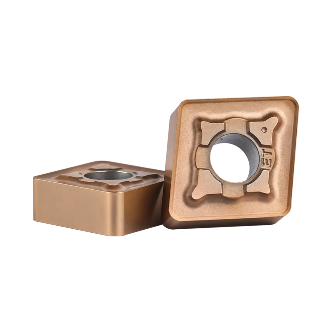
CNMG–ET
CTM9530 — ENGINEERED FOR STAINLESS-STEEL MACHINING.
Introduction
CTM9530 is Carbiforce application-engineered carbide grade platform for Engineered For stainless-steel turning, milling and drilling. It combines a Si-containing AlTiN PVD composite nano-coating, a tough fine-grained carbide matrix, and operation-specific cutting geometries to manage chip formation, concentrated cutting heat, abrasive contact, and changing mechanical loads.
From external turning and high-feed milling to production holemaking, CTM9530 lets engineers select the right geometry for each operation while maintaining one technically aligned coating–substrate platform.
Coating System
Si-Containing AlTiN PVD
Substrate Support
Fine-Grained Carbide Matrix
Cutting Edge Form
Insert Geometry
ENGINEERED FOR STAINLESS-STEEL MACHINING REQUIRES MORE THAN ONE INSERT SHAPE.
Turning, milling and drilling place different mechanical loads on the cutting edge. CTM9530 brings these operations under one grade platform while using application-specific geometries to control chip flow, cutting-force direction, and material engagement.
The coating protects the active edge against concentrated heat and abrasive wear. The fine-grained carbide matrix supports the mechanical load. Each insert geometry then manages the cutting action required by the specific operation.
Coating System
Si-Containing AlTiN PVD
Coating Thickness
3–5 μm Coating Thickness
Surface Hardness
HV 3,200–3,700 Coating Hardness
Operation Coverage
Turning • Milling • Drilling
PARAMETER-PRESENTATION RULE
must be identified as the current turning-grade working range.
These values should not automatically be applied to APMT, LNMU or SPMG inserts.
KEY BENEFITS OF CTM9530
CNMG–ET
CNMG ET CTM9530
Rough stainless-steel turning under higher load and thicker chip formation.
CTM9530 OPERATION FAMILIES
TURNING SOLUTIONS
Product Forms
TNMG • CNMG • WNMG • VNMG
Operations
EXTERNAL TURNING • FACING • PROFILING • BORING
Application Range
FINISHING • MEDIUM TURNING • CONTROLLED ROUGHING
Confirmed Geometry Positioning
TNMG–EA
Medium roughing through finishing with controlled chip formation.
REQUEST A CTM9530 APPLICATION REVIEW
Stainless Steel Machining Inserts
Stainless steel machining requires the right combination of carbide grade, insert geometry, coating, cutting parameters, and tool setup. Incorrect insert selection can lead to excessive tool wear, built-up edge, poor surface finish, chip-control problems, and unplanned production interruptions.
Carbiforce provides carbide cutting tool solutions for industrial machining applications, helping CNC machine shops and manufacturing businesses identify suitable tooling for their workpiece material and machining requirements.
Our range of stainless steel machining inserts supports turning, milling and drilling applications. The right insert depends on the stainless steel grade, operation type, machine rigidity, coolant availability, depth of cut, and required surface finish.
Whether you need carbide inserts for stainless steel production, a suitable turning insert for roughing, or indexable tooling for milling and hole-making, our team can help you evaluate the available options.
Looking for the right insert for your stainless steel component? Share your material grade, operation, current insert model, and machining problem to request a suitable tooling recommendation.
Carbide Inserts for Stainless Steel Machining
Stainless steel is widely used in automotive components, pumps, valves, process equipment, oil and gas components, engineering parts, and general industrial manufacturing.
However, different stainless steel grades can behave differently during cutting. Austenitic grades such as SS304 and SS316 may create long chips and generate substantial heat during machining. Other stainless steel grades can present different challenges depending on their hardness, condition and composition.
Selecting carbide inserts for stainless steel requires more than choosing an insert based on its shape or price. The grade, edge preparation, chipbreaker and cutting conditions must suit the actual operation.
Common Stainless Steel Machining Challenges
Rapid insert wear
Possible cause
Excessive cutting temperature, unsuitable grade or cutting conditions
Practical solution to evaluate
Review grade suitability, cutting speed and coolant application
Built-up edge
Possible cause
Material adhesion, unsuitable cutting speed or cutting-edge geometry
Practical solution to evaluate
Evaluate a suitable sharp geometry, coating and cutting condition
Long, uncontrolled chips
Possible cause
Chipbreaker mismatch, feed or depth-of-cut conditions
Practical solution to evaluate
Select a chipbreaker designed for the operation and chip thickness
Poor surface finish
Possible cause
Worn edge, vibration, incorrect feed or unstable setup
Practical solution to evaluate
Check edge condition, tool overhang, rigidity and feed
Edge chipping
Possible cause
Interrupted cutting, unstable clamping or unsuitable edge strength
Practical solution to evaluate
Evaluate a tougher grade or stronger edge geometry
Short tool life
Possible cause
Incorrect application match or inconsistent cutting conditions
Practical solution to evaluate
Review the complete tooling setup and compare results systematically
| Machining problem | Possible cause | Practical solution to evaluate |
|---|---|---|
| Rapid insert wear | Excessive cutting temperature, unsuitable grade or cutting conditions | Review grade suitability, cutting speed and coolant application |
| Built-up edge | Material adhesion, unsuitable cutting speed or cutting-edge geometry | Evaluate a suitable sharp geometry, coating and cutting condition |
| Long, uncontrolled chips | Chipbreaker mismatch, feed or depth-of-cut conditions | Select a chipbreaker designed for the operation and chip thickness |
| Poor surface finish | Worn edge, vibration, incorrect feed or unstable setup | Check edge condition, tool overhang, rigidity and feed |
| Edge chipping | Interrupted cutting, unstable clamping or unsuitable edge strength | Evaluate a tougher grade or stronger edge geometry |
| Short tool life | Incorrect application match or inconsistent cutting conditions | Review the complete tooling setup and compare results systematically |
The most suitable solution depends on the workpiece and machining conditions. A change in insert grade alone may not solve a problem caused by excessive tool overhang, poor clamping or incorrect cutting parameters.
PVD-Coated Carbide Inserts for Stainless Steel
PVD-coated carbide inserts are commonly considered for applications requiring a combination of wear resistance, edge sharpness, and controlled cutting performance. Their suitability depends on the coating system, carbide substrate, insert geometry, and machining operation.
In stainless steel machining, the cutting edge must handle heat, material adhesion, and cutting forces while maintaining the required component quality.
When Should You Consider a PVD-Coated Insert?
Evaluate PVD-coated inserts when:
PVD Coating Selection Considerations
A coating should not be selected by coating name alone. The coating and carbide substrate must be suitable for the intended operation.
Before choosing an insert, verify:
Solution approach: If your current insert wears quickly or produces inconsistent surface finish, share the insert designation, stainless steel grade, and cutting parameters with our team. This allows the available alternatives to be evaluated against the actual machining problem.
CNC Tools for Stainless Steel Machining
Choosing the correct CNC tools for stainless steel involves selecting the complete cutting system, not just the insert. Tool geometry, holder rigidity, machine condition, coolant delivery and workpiece clamping can all affect machining results.
Carbiforce offers tooling options across multiple machining operations. The appropriate product should be selected according to the component design, operation, and verified material compatibility.
Turning Tools for Stainless Steel
Turning operations may include external turning, facing, internal turning, profiling, and roughing. The selected insert must suit the required cutting action, material condition, and surface-finish requirements.
Related products: Turning Inserts and Turning Tool Holders.
Milling Tools for Stainless Steel
Milling applications include face milling, shoulder milling, slotting and other material-removal operations. Insert geometry, cutter-body compatibility, tooth engagement, and machine rigidity should be considered together.
Related products: Milling Inserts and Indexable Milling Cutters.
Drilling Tools for Stainless Steel
Indexable drilling systems use cutting inserts positioned within a drill body. Central and peripheral inserts may have different functions, and their specifications must match the selected drilling system.
Related products: Drilling Inserts and SPWC U-Drill.
Indexable Inserts for Stainless Steel
Indexable inserts for stainless steel allow users to replace or index a cutting edge instead of replacing the complete tool. They are widely used in production environments where repeatable setup, controlled tooling costs and consistent machining performance matter.
Indexable inserts are available in different shapes, clearances, thicknesses, corner radii, chipbreaker geometries and carbide grades. The correct selection depends on the holder or cutter body and the intended cutting operation.
Important Insert Selection Factors
Workpiece material:
Identify the stainless steel grade and its material condition.
Operation:
Determine whether the application involves turning, milling, drilling, grooving or threading.
Cutting conditions:
Check cutting speed, feed, depth of cut and coolant availability.
Edge strength:
Consider whether the cut is continuous, interrupted or affected by scale and hard spots.
Chip control:
Match the chipbreaker to the expected chip thickness and cutting operation.
Tool compatibility:
Verify the insert designation, dimensions, seating and clamping system.
Production objective:
Balance tool life, component quality, cycle time and tooling cost.
How to Choose an Insert for Production Machining
Start with the insert and grade recommended for your material and operation. Establish a stable baseline using the current cutting conditions, then change one parameter at a time.
Record tool life, number of components per edge, surface finish, cycle time and any rejected components. This makes it easier to identify whether the improvement comes from the insert, cutting conditions or overall setup.
Stainless Steel Turning Inserts for Roughing and Finishing
Stainless steel turning inserts must provide suitable cutting-edge strength, chip control and wear resistance for the selected turning operation. Roughing and finishing typically have different requirements.
Stainless Steel Roughing Inserts
Roughing removes material at a higher material-removal rate. The insert must handle the cutting forces and depth of cut without excessive wear or edge damage.
When selecting stainless steel roughing inserts, consider:
A stronger cutting edge may be appropriate for some demanding conditions, but excessive edge strength or an unsuitable geometry can increase cutting forces. Selection should follow the tooling supplier's application recommendations.
Finishing Inserts for Stainless Steel
Finishing operations focus on dimensional accuracy and surface quality. A suitable geometry, stable cutting edge, correct nose radius and controlled feed are important.
If the component shows poor finish, check the cutting edge, machine vibration, workpiece clamping, feed rate, and tool overhang before changing the insert grade.
TNMG Insert for Stainless Steel
A TNMG insert for stainless steel should be selected by checking the complete insert designation, grade, chipbreaker, and application recommendation.
TNMG inserts have a triangular shape and a negative-clearance design. They are commonly used in suitable external turning setups, but not every TNMG grade or chipbreaker is appropriate for stainless steel.
Before ordering, confirm:
Do not select a TNMG insert for stainless steel based only on the shape designation. The complete insert and grade combination determines suitability.
Chipbreaker Inserts for Stainless Steel Turning
Chipbreaker inserts for stainless steel turning help control the shape and evacuation of chips produced during machining. This is particularly important when machining ductile stainless steel grades that may produce long, continuous chips.
A chipbreaker must work within its intended feed and depth-of-cut range. A geometry designed for light finishing may not control chips effectively during heavy roughing, while a roughing chipbreaker may not provide the desired finishing result.
Light finishing
Suitable sharp geometry and chip control at lower feeds
General turning
A chipbreaker compatible with the normal feed and depth of cut
Heavy roughing
Edge strength and chip control at higher cutting loads
Interrupted cutting
Grade toughness, edge preparation and setup rigidity
Long-chip problems
Chipbreaker range, actual chip thickness and coolant delivery
| Requirement | What to evaluate |
|---|---|
| Light finishing | Suitable sharp geometry and chip control at lower feeds |
| General turning | A chipbreaker compatible with the normal feed and depth of cut |
| Heavy roughing | Edge strength and chip control at higher cutting loads |
| Interrupted cutting | Grade toughness, edge preparation and setup rigidity |
| Long-chip problems | Chipbreaker range, actual chip thickness and coolant delivery |
Machining tip: If chips wrap around the workpiece or tool holder, first verify the chipbreaker application range and actual cutting conditions. Increasing feed without checking the insert recommendation can create additional problems.
Milling Inserts for Stainless Steel
Milling inserts for stainless steel are used in operations such as face milling, shoulder milling and other indexable milling applications. The best option depends on the cutter body, insert geometry, stainless steel grade, and required material-removal rate.
During stainless steel milling, heat generation, work hardening, interrupted cutting and chip evacuation can affect insert life. A suitable insert must balance edge strength, cutting forces and the desired surface finish.
APMT Insert for Stainless Steel
An APMT insert for stainless steel must be selected according to its exact model, grade, geometry, and compatible cutter body.
APMT is an insert designation, not a guarantee of stainless steel compatibility. Different APMT inserts can have different geometries, clearances, coatings, and application recommendations.
Before selecting an APMT insert, verify:
For stainless steel milling, avoid selecting an insert solely because the same shape is already used for steel. Confirm that the specific grade is approved for the intended stainless steel application.
Improving Stainless Steel Milling Performance
If your milling operation experiences premature edge wear, chipping or vibration, evaluate the following:
Related product: Carbiforce Milling Inserts.
Drilling Inserts for Stainless Steel
Drilling inserts for stainless steel are used in compatible indexable drilling systems to produce holes in production machining. The selected insert must match the drill body and the requirements of the workpiece material, hole diameter and drilling depth.
Central and Peripheral Drilling Inserts
Some indexable drill systems use separate central and peripheral inserts. Their cutting conditions and functions differ, so they must be selected as a compatible system.
When choosing drilling inserts, evaluate:
If chips pack inside the hole or the drill experiences premature wear, review coolant delivery, chip evacuation, the insert grade, and the recommended cutting parameters.
Solution approach: Share your drill model, required hole diameter, drilling depth and stainless steel grade to identify suitable available insert options.
Best Carbide Insert for Stainless Steel Machining
As For best carbide insert for stainless steel machining for every operation. The most suitable insert depends on the material, cutting operation, machine conditions, chip-control requirements and production objective.
An insert that performs well during continuous turning may not be suitable for interrupted milling. Likewise, a finishing geometry may not withstand the demands of heavy roughing.
Insert Selection by Machining Requirement
General stainless steel turning
Selection priority
Material-compatible grade and stable chip control
Information to verify
Workpiece grade, turning conditions and chipbreaker
Heavy turning or roughing
Selection priority
Suitable edge strength and toughness
Information to verify
Depth of cut, interruptions and machine rigidity
Fine turning and finishing
Selection priority
Controlled cutting action and surface quality
Information to verify
Feed, nose radius, workpiece support and edge condition
Stainless steel milling
Selection priority
Compatible insert and cutter system
Information to verify
Cutter model, grade, feed per tooth and engagement
Stainless steel drilling
Selection priority
Compatible central/peripheral insert system
Information to verify
Drill model, diameter, depth and coolant
Repeated production runs
Selection priority
Consistent tool life and process stability
Information to verify
Components per edge, cycle time and quality records
| Machining requirement | Selection priority | Information to verify |
|---|---|---|
| General stainless steel turning | Material-compatible grade and stable chip control | Workpiece grade, turning conditions and chipbreaker |
| Heavy turning or roughing | Suitable edge strength and toughness | Depth of cut, interruptions and machine rigidity |
| Fine turning and finishing | Controlled cutting action and surface quality | Feed, nose radius, workpiece support and edge condition |
| Stainless steel milling | Compatible insert and cutter system | Cutter model, grade, feed per tooth and engagement |
| Stainless steel drilling | Compatible central/peripheral insert system | Drill model, diameter, depth and coolant |
| Repeated production runs | Consistent tool life and process stability | Components per edge, cycle time and quality records |
Stainless Steel Machining Solutions for Industrial Buyers
Carbiforce supports industrial buyers and machining teams in evaluating cutting-tool options for their applications. The objective is to identify suitable tooling based on the machining requirement rather than recommending an insert without understanding the problem.
Solutions for Common Production Problems
Problem: Inserts wear too quickly
Review the workpiece material, insert grade, cutting speed, coolant conditions, and tool setup. A more suitable grade or revised cutting conditions may improve performance.
What to Share for a Tooling Recommendation
To help evaluate a suitable stainless steel machining insert, provide:
This information helps the technical team assess suitable options and identify which parameters should be reviewed during a machining trial.
Stainless Steel Machining Inserts Supplier in India
Carbiforce serves industrial customers looking for carbide cutting tools and application-focused tooling support. Buyers can discuss their requirements for turning, milling and drilling inserts, along with compatible holders and indexable tooling systems.
As a stainless steel machining inserts supplier in India, the focus is on helping customers identify the right product for their application, verify compatibility and obtain a quotation based on their required models and quantities.
What Industrial Buyers Should Check Before Ordering
Stainless Steel Machining Inserts Manufacturer in India — What Should Buyers Verify?
Buyers searching for a stainless steel machining inserts manufacturer in India should verify the company's actual manufacturing role, product specifications, quality documentation, technical support and supply capabilities.
Carbiforce can be approached for its available cutting-tool range and machining-solution requirements. For manufacturing-specific enquiries, confirm the relevant product's manufacturing origin and supply arrangement directly with the company rather than assuming that every supplier manufactures the products it offers.
Frequently Asked Questions About Stainless Steel Machining Inserts
The suitable insert depends on the stainless steel grade, operation, cutting conditions and required surface finish. Check the insert grade, geometry, coating and chipbreaker recommendations for the exact application.
Contact Carbiforce to discuss product availability, technical requirements and bulk-order enquiries.